
MWS Wire /
Coils provide the magnetic field of motors, transformers, and generators, and are used in the manufacturing of loudspeakers and microphones. The shape and dimension of the wire used in a coil winding are designed to fulfill a specific purpose.
Parameters such as inductance, energy loss ( Q factor), insulation strength, and strength of the desired magnetic field greatly influence the design of coil windings.
Efficient coils minimize the materials and volume required for a given purpose. The ratio of the area of electrical conductors, to the provided winding space is called “fill factor”. Since round wires will always have some gap, and wires also have some space required for insulation between turns and between layers, the fill factor is always smaller than one. To achieve higher fill factors, rectangular, square or flat wire can be used.
MWS skilled technicians produce the highest-quality magnet wire used in custom windings. To speak with a sales representative, contact us regarding your requirements.
Trends in Coil Winding call for custom construction, tight specifications and high-quality spooling.
 Square magnet wire is useful where space constraints are concerned. When formed into a coil an equivalent amount of square wire put in a coil can be placed in a tighter coil configuration than the same amount of round wire. This enables engineers to create compact coils and small motors that deliver more power in less space. The opposite of this would be a random wire structure within the winding space, which is called “wild winding.”
For greater efficiency and reduced heat, dense packing of wires reduces air space and enables a higher fill factor. For best packing of round wires on a multi-layer winding, the wires in the upper layer are in the grooves of the lower layer for at least 300 degrees of the coil circumference. The wires occupy a dense package which is called “Orthocyclic winding”.

Wild Winding
Sometimes called jumble winding, this type of winding structure results in poor fill factors. The random wire placement leads to a wider distribution of resulting wire length on the coil body and consequently a wider range of electric coil resistances. Despite these disadvantages, it is common in mass production and can be wound with very high speeds and requires very little attendance of the operator or the machine used to produce it. Windings are found mostly in relay coils, small transformers, Ignition coils, small electrical motors, and generally devices with relatively small wire gauges up to 0.05 mm. Achieved fill factors with the use of round wires are about 73% to 80% and are lower compared to Orthocyclic windings with a 90% fill factor.

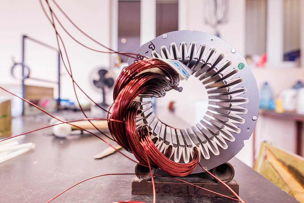
Toroidal Coil Winding Wire
Toroid coils are used when working with electricity that has a low frequency. The toroid functions as an inductor, which boosts the frequency to appropriate levels. Inductors are electronic components that are passive, so that they can store energy in the form of magnetic fields. A toroid turns, and with those turns induces a higher frequency. Toroids are more economical and efficient than solenoids. Toroidal winding is created by winding copper wire through the circular ring and evenly distributing it over the circumference. Despite the high level of manual work due to the low magnetic flux leakage (MFL – Leakage inductance), Toroidal winding produces low core losses and the power density.

Electronically Commutated (EC) Motors
Because of the need for higher performance density in motor winding technology, brushless EC (electronically commutated motors) drives with permanent magnet rotors are increasingly used instead of the asynchronous technology. Due to the compact design, the copper content can in many cases be cut in half.
Manufacturers of electric motors also demand more flexibility of the production technology. For producing asynchronous motors, drawing-in systems are usually used that are initially winding air-core coils only to draw them later into the stator with a tool. In contrast, the concentrated winding of EC stators is more flexible in the manufacturing process, energy saving when implemented, better adjustable during operation and it requires less space.

Helical winding
The wires are placed helically in every layer. Owing to the direction of movement from layer to layer changing between right-hand and left-hand, the wires cross and locate themselves within the gap of the layer underneath. A wire guiding of the lower layer is not existent. If the number of layers exceeds a certain limit, the structure cannot be maintained and a wild winding is created. This can be prevented with the use of a separate layer insulation, which is needed anyway when the voltage difference between the layers exceeds the voltage strength of the copper wire insulation.

Orthocyclic winding
Orthocyclic winding structure creates an optimal fill factor (90.7%) for round wires. The windings of the upper layer need to be placed into the grooves provided by the lower layer.
The best volume use is found when the winding is parallel to the coil flange for most of its circumference. When the winding has been placed around the coil body it will meet with the previous positioned wire and needs to make a step with the size of the wire gauge. This movement is called winding step. The winding step can occupy an area of up to 60 degrees of the coil circumference for round coil bobbins and takes one side of rectangular coil bobbins. The area of the winding step is dependent on the wire gauge and coil bobbin geometry.

If the winding step cannot be executed properly then the self-guiding ability of the wire is lost, and a wild winding is produced. Overall, the first intruding wire mainly determines the location and quality of the winding step. It should be recognized that the wire needs to enter in a possibly flat angle into the winding space. That way an unnecessary bending of the wire is being avoided and the needs space for the second winding step is minimized.
For Orthocyclic wound coils, the winding step areas is always located at the area of wire entering the winding space and is continued in helical form against the winding direction. Consequently, a larger winding width of the coil leads to a bigger winding step area along the circumference of the coil. The created offset leads to a different position of the layer step, from the first to the second layer, in comparison to the wire entry. This behavior repeats itself with every layer which leads to a spiral shaped crossover section at the side of the winding. When wires are crossing within the crossover section the resulting winding height is increased. As a result, Orthocyclic wound coils with a round coil ground are never circular in the cross over section, but the radial moving winding and layer step creates a hump shape. Experience has shown that depending on the winding width, coil and wire diameter, the crossover section is about 5 to 10 percent higher than the regular winding height.
Three Wire Winding Geometries
Ideally, the winding should be positioned parallel to the winding flange, meeting an orthogonality condition. It is necessary to adjust the winding width to the number of turns per layer of the winding. For non-circular shaped coil cross-sectional areas, it is preferable to locate the crossover area to the small side of the coil body, also called winding head. This is because the non-circular coils are being mounted on a sheet metal package or in a circular arrangement. The coils should be rather small, in order to avoid a contact with the neighboring coil or the sheet metal package. For Orthocyclic round coils, three winding geometries can be defined:

1. Equal number of turns per layer

2. Unequal number of turns per layer, starting with shortened layer

3. Unequal number of turns per layer, starting with longer layer
The choice of the winding structure to be used basically depends on the design of the coil or the coil body. Among others, the available space conditions for winding width and winding height must be considered. Moreover, it is possible to influence the location and the end of the last winding by selecting a clever winding pattern. The winding height of an Orthocyclic coil winding results from the following equation:
h = [1+(n-1) – sin 60° – d
h – Winding height
n – Number of layers
d – max. wire gauge above the varnish (CuL)
An Orthocyclically wound coil with at least 300° of the circumference of winding layers has the tightest circle package of the wire cross-sections. This winding method reaches the highest fill factor and is the best way to fill the available winding cross-section with round wires. Square coils are seen as Orthocyclically wound when the winding and layer jump occur only on one of the sides of the winding cross-section.
In theory, a geometric fill factor of 0.91 will be reached. In practice, however, the value cannot be reached because there exists a winding jump and layer jump area and the wire insulation is not taken into account.
